DA3 Is About Reciprocating Compressor Piping
A reciprocating compressor does not deliver a continuous stream of gas. Each cylinder draws in and discharges a finite volume on every revolution, creating periodic pressure waves in the suction and discharge systems. Those waves reflect at vessels, branches, valves, restrictions, and changes in pipe area. When an acoustic response aligns with a forcing frequency, pressure pulsation and unbalanced shaking forces can increase sharply.
The piping then has its own mechanical natural frequencies. If an acoustic shaking force excites one of them, the result can be high vibration, cyclic stress, failed small-bore connections, cracked welds, damaged instruments, loosened supports, or repeated commissioning modifications.
API Design Approach 3—normally shortened to DA3—is the study level used to evaluate this coupled problem for reciprocating machinery systems. It is not a compressor performance simulation, a foundation dynamic analysis, or a centrifugal-compressor rotordynamic study. Its central purpose is to show that pressure pulsations, shaking forces, piping response, and cyclic stresses remain acceptable across the specified operating envelope.
This article explains when DA3 is required, when a purchaser should specify it even if the minimum selection route permits a lower approach, and what the project must provide to make the analysis useful. For the machine-selection context, see Reciprocating vs Centrifugal Compressors.
Standards Basis: API 618 and API 688
The current published basis is the current edition of API Standard 618, for reciprocating compressors in petroleum, chemical, and gas-industry services, used with the current edition of API RP 688, for pulsation and vibration control in positive-displacement machinery systems.
Project specifications may still invoke earlier editions, company standards, or additional requirements. The purchase order governs. Before deciding the analysis scope, the purchaser, packager, and analyst should record:
- Applicable standard and edition
- Purchaser's compressor datasheet selections
- Any owner-company override or project specification
- Required operating and upset cases
- Acceptance criteria and reporting requirements
- Responsibility for bottle, piping, support, skid, and foundation models
The standards are copyrighted engineering documents. A project should use its licensed copies and the exact selection procedure applicable to the contracted edition. A blog summary—or a vendor's standard proposal note—is not a substitute for completing that procedure.
The important practical point is that DA3 selection has two layers:
- The minimum approach determined by the governing standard and purchaser datasheet.
- Any higher approach selected by the purchaser because the service, layout, uncertainty, or consequence warrants it.
DA3 can therefore be required even when a simple screening description of power or pressure would suggest otherwise.
DA1, DA2, and DA3: What Changes?
The three approaches represent increasing analytical depth. They should not be treated as three grades of pulsation bottle.
Design Approach 1
DA1 uses simplified or empirical pulsation-control methods suited to lower-risk applications within the approach's permitted range. The supplier designs the pulsation suppression devices and piping arrangement to the applicable rules, but does not perform the full system acoustic and mechanical response analysis associated with DA3.
Its advantage is speed and lower engineering cost. Its limitation is that it does not explicitly predict the coupled response of the actual compressor, bottles, piping, branches, restrictions, supports, and operating cases.
Design Approach 2
DA2 introduces a digital acoustic simulation. The model predicts pressure pulsations and acoustic shaking forces through the compressor piping system across the required frequencies and operating cases. The analyst can adjust bottle geometry, internal choke tubes, orifices, piping lengths, and arrangements to control the acoustic response.
DA2 answers the question: what pressure pulsations and shaking forces will the gas system generate?
It does not, by itself, fully answer how the actual piping structure responds to those forces.
Design Approach 3
DA3 combines the acoustic work with a mechanical response analysis. Acoustic shaking forces are applied to a mechanical model representing piping mass, stiffness, supports, vessels, bottles, compressor connections, and other relevant structural boundaries. The analysis predicts vibration response and cyclic stress and identifies mechanical resonances or weak configurations.
DA3 answers both questions:
- What forces does the pulsating gas generate?
- How does the real piping and support system respond to those forces?
This second question is why support type, stiffness, location, gaps, clamps, bottle supports, skid interfaces, and branch geometry cannot be left undefined until construction.
| Approach | Acoustic model | Mechanical response model | Best suited to |
|---|---|---|---|
| DA1 | Simplified/empirical control | No full forced-response model | Eligible lower-risk, simpler systems |
| DA2 | Detailed digital analysis | Limited mechanical review rather than full response model | Systems needing acoustic optimisation |
| DA3 | Detailed digital analysis | Detailed mechanical natural-frequency and forced-response analysis | Higher-risk, complex, critical, or purchaser-selected systems |
The contracted standard defines the precise scope and acceptance requirements. The table above explains the engineering distinction, not the contractual detail.
When DA3 Is Formally Required
DA3 is formally required when the selection method in the specified API edition, completed with the actual compressor and service data, selects Design Approach 3—or when the purchaser marks DA3 as required in the datasheet or project specification.
The selection process considers machinery and service severity rather than compressor name alone. Depending on the governing edition and project requirements, relevant inputs include compressor power, pressure level, speed, cylinder arrangement, service, and other defined parameters.
This means there is no reliable universal statement such as:
“All compressors above X kW require DA3.”
That shortcut can fail in both directions. A machine below an assumed power threshold may have a difficult high-pressure, variable-speed, shared-header system. A larger but slow, simple, single-case machine may be less acoustically complex. The current decision must be made using the actual standard selection process and purchaser requirements.
The DA approach should be fixed in the requisition. Leaving it for the successful vendor to decide after award creates a commercial conflict: the study becomes an unpriced addition precisely when the project has the least leverage and the layout is becoming harder to change.
A Practical DA3 Decision Aid
The workflow below separates the contractual minimum from the purchaser's engineering judgement. The first two gates are mandatory: apply the selection procedure from the licensed standard edition named in the project and check the purchaser or company specification. Only after those gates does the project consider whether risk modifiers justify escalating to DA3.
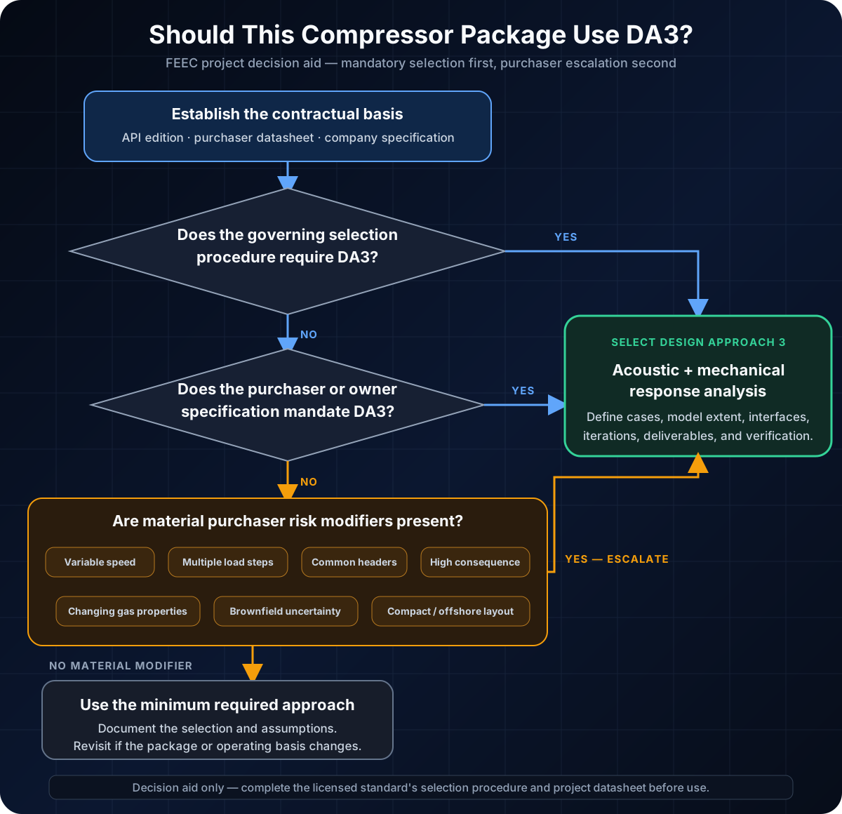
The risk-modifier gate is deliberately qualitative. Variable speed or brownfield work does not automatically create a new API mandate, but it can make a mechanical response analysis prudent. The purchaser should record the reasons for either escalation or retention of the minimum approach and revisit the decision if the operating envelope, piping layout, or package configuration changes.
When the Purchaser Should Specify DA3 Anyway
The minimum approach is not always the appropriate project approach. DA3 is a sensible purchaser requirement when one or more of the following materially increases uncertainty or consequence.
Variable-speed operation
A fixed-speed machine has discrete forcing frequencies. A variable-speed machine sweeps those frequencies across a band, increasing the chance of crossing acoustic or mechanical resonances. The analysis must evaluate the continuous or discrete operating-speed range, prohibited-speed regions, start-up passage, and expected dwell time.
Multiple load steps and operating cases
Suction-valve unloaders, clearance pockets, deactivated cylinder ends, recycle operation, changing gas composition, and seasonal pressures alter the excitation pattern and system response. A model checked only at rated flow can miss a governing part-load case.
Multiple compressors on common headers
Parallel units can interact through common suction or discharge piping. Running one, two, or several machines—and operating nominally identical machines with slight speed differences—creates more cases and possible beat behaviour. Unit isolation and future expansion configurations also matter.
High-pressure or high-ratio service
Higher gas density and pressure can increase the energy associated with pulsation and the consequence of piping fatigue. Multi-stage compressors also create several interconnected systems with interstage coolers, scrubbers, relief paths, and recycle connections.
Light gas or changing composition
Hydrogen-rich, helium-rich, or compositionally variable gases change acoustic velocity and therefore resonant frequencies. A design optimised for one molecular weight may perform differently at another. The analysis should cover the credible gas-property envelope.
Brownfield connections
Existing piping stiffness, support condition, wall thickness, restraint gaps, and boundary behaviour may be uncertain. A new compressor can excite an old header that was never designed for its forcing spectrum. Field survey and vibration data become as important as drawings.
Compact or offshore layouts
Weight and space constraints encourage short pipe runs, shared structures, tightly packed branches, and support compromises. Skid and module flexibility can affect boundary conditions. Late pipe-support additions may be physically impossible.
Critical or unspared service
If a vibration failure stops production, removes the only compression train, or creates a high-consequence loss of containment, the cost of deeper analysis is small compared with the exposure. Reliability and consequence can justify DA3 even when the minimum selection route does not.
Unusual bottle or piping geometry
Compact bottles, complex internals, non-standard branches, large side nozzles, close-coupled coolers, long unsupported runs, or high small-bore-connection density all strengthen the case for explicit acoustic–mechanical verification.
These factors do not automatically redefine the standard's mandatory selection. They are purchaser reasons to choose a more rigorous scope.
What the Acoustic Model Must Include
The acoustic model represents the gas passages from the cylinder valves through the pulsation bottles and connected piping to boundaries that behave predictably. The model should be detailed enough to reproduce the geometry that controls wave propagation and reflection.
Inputs normally include:
- Cylinder bore, stroke, rod diameter, clearance, and valve information
- Compressor speed range and phasing
- Active and unloaded cylinder-end configurations
- Gas composition and thermodynamic properties for every case
- Suction, interstage, and discharge pressures and temperatures
- Bottle volumes, nozzle geometry, choke tubes, baffles, and internal restrictions
- Pipe lengths, diameters, wall thicknesses, branches, reducers, and fittings
- Coolers, scrubbers, valves, orifices, relief connections, recycle tie-ins, and headers
- Boundary conditions at vessels, large headers, or defined termination points
The model predicts pressure pulsation at selected locations and the differential pressure acting across piping elements. From this, the analyst determines acoustic shaking forces. A local pulsation amplitude that appears acceptable can still generate a significant force across a large-area discontinuity, so reviewing pressure plots alone is not enough.
The acoustic design is iterative. Bottle volume, internal arrangement, orifice size, and piping geometry may be adjusted to reduce response. Every restriction has a cost: permanent pressure drop, compressor power, heat, erosion potential, and turndown behaviour. The solution is not to suppress pulsation at any price; it is to meet acceptance criteria with an operable and efficient system.
What the Mechanical Model Must Include
The mechanical model converts the piping arrangement into mass and stiffness. It should represent the system the construction team will actually build, including:
- Compressor cylinder and distance-piece connection boundaries
- Pulsation bottles and their supports
- Process piping, flanges, valves, reducers, and concentrated masses
- Scrubber and cooler nozzles where they influence response
- Primary supports, guides, anchors, clamps, hold-downs, and braces
- Support stiffness in the relevant directions
- Skid, deck, sleeper, or foundation interfaces where flexibility matters
- Small-bore branches included by the agreed screening criteria
The model first identifies mechanical natural frequencies and mode shapes. Separation checks compare these with compressor forcing frequencies and relevant excitation bands. Where separation alone is insufficient or impractical, forced-response analysis applies predicted acoustic forces and calculates vibration amplitude and cyclic stress.
Support labels such as “guide” or “rest” are not enough. A guide with a gap responds differently from a rigid clamp; a U-bolt responds differently from a fitted dynamic restraint; a support on a flexible skid beam does not behave like one attached to an infinitely rigid foundation. The analyst needs realistic stiffness and restraint assumptions, and the drawings must preserve them.
Operating Cases: Rated Duty Is Not Enough
The DA3 case matrix should be agreed before modelling begins. It usually spans:
- Minimum, normal, and maximum compressor speed
- Rated and alternate suction/discharge pressures
- Start-of-life and late-life field conditions
- Minimum and maximum gas molecular weight or acoustic velocity
- Each planned capacity-control step
- Single- and multiple-unit operation on shared headers
- Recycle, start-up, unload, or temporary operating modes that have meaningful dwell time
- Future operating cases committed by the project
The governing acoustic case and governing mechanical case may differ. Maximum pressure may produce the largest force, while a lower-speed part-load condition aligns more closely with a piping natural frequency. A summary that reports only the rated point hides this distinction.
Temporary conditions should be treated proportionately. A machine may pass quickly through a resonant speed during start-up without accumulating damaging fatigue, but it may not be acceptable to dwell there continuously. Where a prohibited-speed band is proposed, it must be compatible with the driver, controls, operating procedures, and process requirements.
DA3 Is Not a Torsional or Foundation Study
Several analyses around a reciprocating compressor are related but distinct:
- Torsional analysis evaluates the crankshaft, driver, coupling, flywheel, and driven-train torsional response.
- Compressor frame and foundation analysis evaluates dynamic forces and moments transmitted into the skid, concrete, piles, or supporting module.
- Nozzle-load and piping flexibility analysis evaluates thermal, weight, pressure, and displacement loads as well as applicable occasional cases.
- Small-bore connection assessment evaluates local branch vibration susceptibility and fatigue.
- DA3 pulsation and vibration analysis evaluates acoustic excitation and the mechanical response of the connected gas piping system.
These studies exchange data, but one does not automatically satisfy another. The project responsibility matrix should name who owns each analysis and how interface loads and stiffnesses are transferred.
Project Timing: Start Before the Layout Freezes
DA3 creates value only while the design can still change.
Requisition stage
Specify the governing editions, DA3 requirement, operating cases, model extent, deliverables, review cycle, analyst qualifications, and responsibility split. Require the vendor to price design iterations—not only one final report.
Post-award design basis
The compressor vendor provides cylinder, valve, speed, load-step, gas, and preliminary bottle data. The EPC or piping designer provides the plot arrangement, piping philosophy, equipment locations, and boundary information. The analyst issues an input-data register with missing items and assumptions.
Preliminary acoustic study
Acoustic work can begin while bottle and piping geometry are still adjustable. Early findings influence bottle configuration, nozzle locations, minimum straight lengths, orifice requirements, and major routing.
Mechanical model stage
The piping layout and support concept must be mature enough to model, but not issued for construction. DA3 recommendations are incorporated into piping isometrics, support drawings, bottle drawings, skid interfaces, and structural design.
Final verification
The analyst checks the frozen vendor and piping geometry. Every deviation from the analysed configuration is resolved through a controlled change process. “Similar to the model” is not an acceptance criterion when support stiffness or pipe length changes a natural frequency.
Construction and commissioning
Site verification confirms support type, location, gaps, clamp fit, bottle installation, and piping line-up. Baseline vibration measurements during staged commissioning test the predicted operating cases and provide a reference for future condition monitoring.
Running DA3 after isometrics are issued for construction converts design optimisation into field rework. That is the most expensive way to use the study.
The Interfaces That Commonly Break
DA3 sits between organisations that do not always share the same model or schedule.
| Party | Essential responsibility |
|---|---|
| Purchaser/operator | Define standard edition, DA approach, operating envelope, acceptance expectations, and future cases |
| Compressor vendor/packager | Supply machine excitation data, cylinder configuration, bottles, skid interfaces, and package geometry |
| Specialist analyst | Build and document acoustic/mechanical models, identify governing cases, and issue actionable recommendations |
| EPC process team | Supply gas cases, pressures, temperatures, compositions, control modes, and relief/recycle configurations |
| EPC piping team | Supply routing, dimensions, valves, branches, support concept, and incorporate model requirements |
| Structural/civil team | Confirm support, skid, deck, and foundation stiffness and loads |
| Construction team | Install the analysed configuration and control deviations |
| Commissioning/operations | Test cases safely, record vibration baseline, and observe prohibited operating regions |
A frequent failure is a vendor scope that ends at the skid edge while the analyst assumes the first off-skid anchor is rigid. The EPC later moves that anchor or mounts it on flexible steelwork, changing the mechanical system without reopening the study. Model boundaries must be physical, documented, and owned.
What a Complete DA3 Report Should Contain
A useful report allows the purchaser to understand what was modelled, what governs, and what must appear on the drawings. It should include:
- Applicable standards, editions, project specifications, and deviations
- Approved input register and data sources
- Compressor configuration, speed range, cylinder phasing, and capacity-control cases
- Gas properties and process conditions for each case
- Acoustic model extent, node diagram, boundaries, and assumptions
- Predicted pulsations, pressure drop, and shaking forces
- Mechanical model extent, mass, support, stiffness, and boundary assumptions
- Natural frequencies and relevant mode shapes
- Forced vibration and cyclic-stress results where required
- Governing case and acceptance comparison for each result
- Required bottle internals, orifices, piping dimensions, and support details
- No-change dimensions or stiffness requirements that must be controlled
- Sensitivities, unresolved inputs, exclusions, and residual risks
- A recommendation register that maps each action to a drawing or responsible party
- Final model files and revision suitable for future modifications
Colour plots are not a design deliverable by themselves. Recommendations must be expressed as buildable requirements: support coordinates, restraint direction, minimum stiffness, maximum gap, pipe schedule, bottle internal dimension, orifice bore, or controlled pipe length—with tolerances where sensitivity warrants them.
How to Review a Vendor DA3 Proposal
Before award, check whether the proposal answers these questions:
- Does it cite the correct API 618 and API 688 editions?
- Is DA3 explicitly included, or only an “API pulsation study”?
- Are both acoustic and mechanical response analyses included?
- What are the model boundaries on suction, interstage, discharge, recycle, relief, and common headers?
- How many compressor configurations, gas cases, speed cases, and load steps are included?
- Are shared-header and multiple-unit cases included?
- Who supplies support stiffness and who verifies the supporting structure?
- How many design iterations are included before additional charges apply?
- Are final as-built changes and commissioning support included?
- Are model files delivered, and in what format?
- Does the analyst have authority to place requirements on vendor and EPC drawings?
The cheapest line item may exclude precisely the cases or off-skid piping most likely to govern. Compare scope before price.
Illustrative Case: Variable-Speed Gas Booster
Consider a three-stage reciprocating gas booster driven by a variable-speed electric motor. The package operates from 600 to 900 rpm, compressing gas from approximately 8 barg to 70 barg. Field decline changes suction pressure and gas molecular weight over time, and two identical packages connect to common suction and export headers.
The rated point alone is not a sufficient basis. The case matrix includes:
- Minimum, normal, and maximum speed
- Start-of-life and late-life suction conditions
- Two gas compositions
- Full-load and planned unloaded-cylinder configurations
- One package operating and both packages operating
- Recycle operation during start-up and process turndown
The preliminary acoustic model identifies a strong response near a running-speed harmonic in the second-stage discharge system. The highest acoustic force does not occur at maximum speed; it occurs at an intermediate speed with one cylinder end unloaded. The original bottle outlet and spool arrangement creates a large differential pressure across an elbow pair.
The mechanical model then shows that a lateral piping mode lies close to the same excitation band. Simply adding a support at the nearest convenient steel beam does not solve the problem because the beam is flexible in the response direction.
The design is corrected before fabrication by adjusting the bottle internal arrangement, controlling one spool length, and replacing the proposed guide with a braced clamp of defined lateral stiffness. The revised analysis meets pulsation, vibration, and cyclic-stress criteria across the case matrix without creating an unacceptable permanent pressure drop.
The lesson is not that every resonance needs a larger bottle or more steel. DA3 identifies the interacting acoustic and mechanical mechanisms so the project can change the right feature while change is still inexpensive.
Brownfield DA3 Requires Field Evidence
For a new compressor connected to existing piping, drawings are only a starting point. The study should include a field survey covering:
- Actual pipe route, size, schedule, fittings, and branch locations
- Support type, condition, gaps, looseness, corrosion, and foundation attachment
- Unmodelled valves, drains, vents, instruments, and temporary modifications
- Existing vibration measurements and recurring failure locations
- Operating combinations of existing and new machines
- Wall-thickness or integrity data where mass and fatigue assessment depend on it
Impact testing or other modal measurements can help calibrate uncertain mechanical boundary conditions. Baseline pressure pulsation and vibration data from the existing system can also validate model behaviour.
A brownfield report should distinguish surveyed facts from inferred properties. Assuming every support on an old isometric is rigid and present produces a precise model of a facility that does not exist.
Common DA3 Failures
- Selecting the approach after vendor award. The scope becomes a variation and the layout is already constrained.
- Using a power threshold from memory. The governing edition and purchaser datasheet—not folklore—determine the minimum approach.
- Analysing only the rated point. Variable speed, unloaders, alternate gas, and shared-header combinations can govern.
- Stopping the model at the skid edge. Off-skid piping and common headers may contain the critical mode.
- Treating supports as coordinates only. Direction, stiffness, gap, clamp fit, and supporting steelwork determine response.
- Completing acoustic analysis without mechanical response. That is not a complete DA3 assessment.
- Confusing DA3 with torsional or foundation analysis. Each addresses a different dynamic system.
- Accepting pressure pulsation plots without shaking-force review. Acceptable local amplitude does not guarantee low force across every discontinuity.
- Adding orifices without checking pressure drop. Pulsation control must not consume unacceptable compressor power or capacity.
- Ignoring drawing changes after the report. A moved support or revised spool can invalidate the analysed configuration.
- Skipping site verification. The model is only as good as the system actually installed.
- Treating commissioning vibration as the first design check. Field measurement verifies the design; it should not replace it.
Conclusion
DA3 is required when the governing API selection procedure or purchaser specification calls for it. But the better engineering question is whether the project needs a coupled acoustic and mechanical response analysis to control a credible vibration and fatigue risk.
Variable speed, multiple load steps, shared headers, changing gas composition, high-pressure service, brownfield uncertainty, compact layouts, and high production consequence all strengthen the case for a purchaser-specified DA3 study. None should be reduced to a universal horsepower slogan.
The study must also be timed correctly. Specify it in the requisition, start the acoustic work while bottles and routing can change, complete the mechanical model before supports and isometrics freeze, control deviations, and verify the installed arrangement during commissioning.
Done this way, DA3 is not a report added to a vendor document register. It is a design process that converts a pulsating compressor into a piping system that can operate across its full envelope without becoming a vibration problem the site has to redesign after start-up.